As a Structures and Material Science Designer for the 2022-23 SAE Aero Regular class season, there were many design challenges that I got to work on. The plane design for the 2022 season is particularly impressive because the 18-foot wingspan and large fuselage capacity allowed the plane to carry weight capable of reaching the FAA limit of 55 pounds and made this plane the biggest in Texas A&M history. In addition, our team had to make sure all design decisions followed the annually updated ruleset.


Vivify Scrum Software was used to manage the project with an Agile philosophy. Agile models call for iterative development that aims to get an early prototype of a new product or service out into customers’ hands as quickly as possible, in our case we iterated on different designs to get as many flight tests as possible. Slack was used for team communication.
Since the annual ruleset had not been released yet for the 2023 season, our team decided to work the entirety of the summer brainstorming new designs based on previous years' ideas and begin CAD development for airplane structures. This period marked my first stage within my team's development and served as a major introduction for aeronautical design.
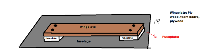
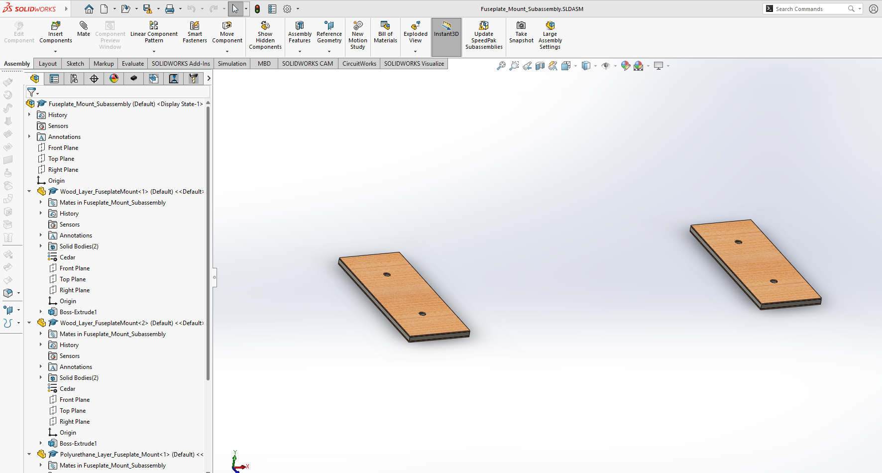
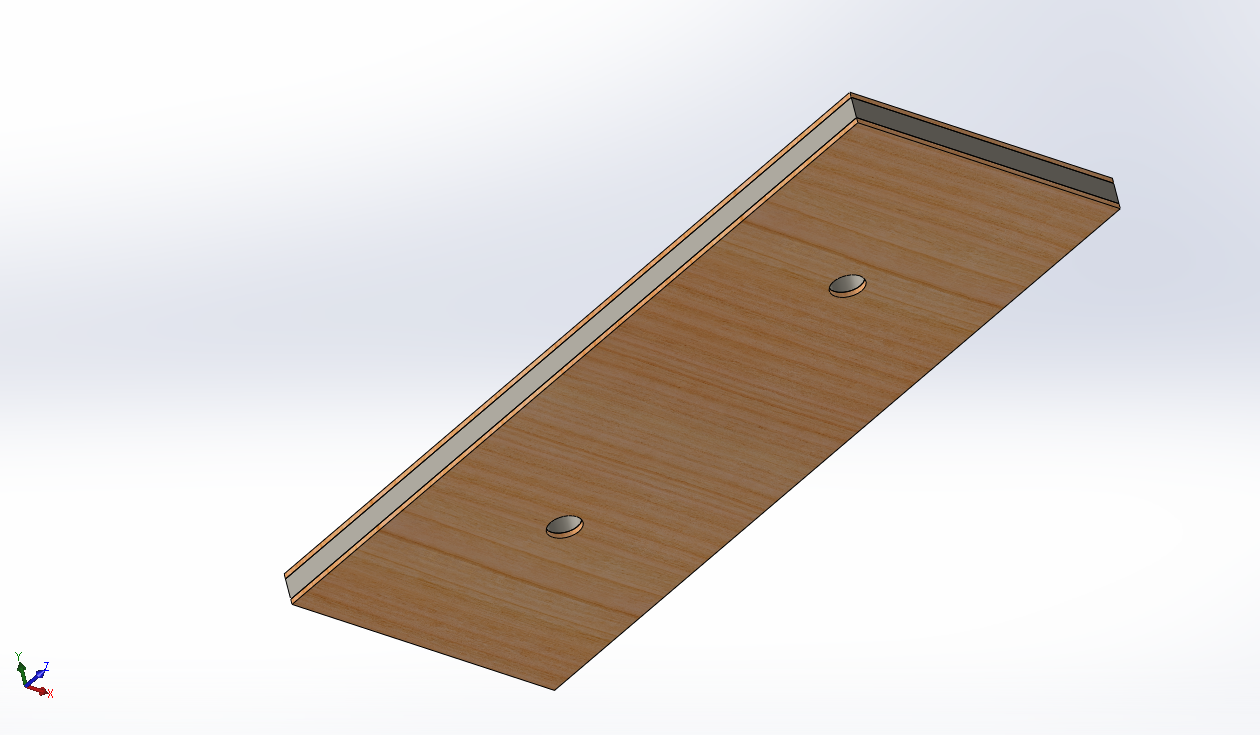
The very first simple project I worked on were the fuseplates that would be utilized as a load-bearing intermediary between the fuselage and bottom of the plane's wingplate. It was important that the geometry of the fuseplate matched the contact area of the wingplate edges and that they distribute stress evenly. The fuseplate pretty much acts like a very large wooden sandwich washer. As shown in the images, the exterior layers of the sandwich structure was comprised of existing cedar wood laying around the shop and polyeurethane as the core. Cedar was chosen for its decent strength-weight ratio and helps with bending resistance and deformation. Polyurethane was chosen for its energy-absoprtion and lightweight properties.
Another project I worked on in the summer was designing the wing ribs for our summer plane that involved a forward-swept wing design. The airfoil profile coordinates were obtained from the NACA database and exported as a .csv file containing coordinates of the airfoil profile. The tabular data was then imported into the SolidWorks Curve function. This established the overall contour of the wing and ensured the desired aerodynamic characteristics. Unfortunately, I do not recall the specific NACA 'XXXX' variant! The ribs were spaced evenly along the span of the wing for uniform pressure load distribution during flight. The root chord was scaled up from the original NACA coordinates then lofted to a tip plane. This design laid the foundation for creating future iterations of lightweight and structurally sound wings.
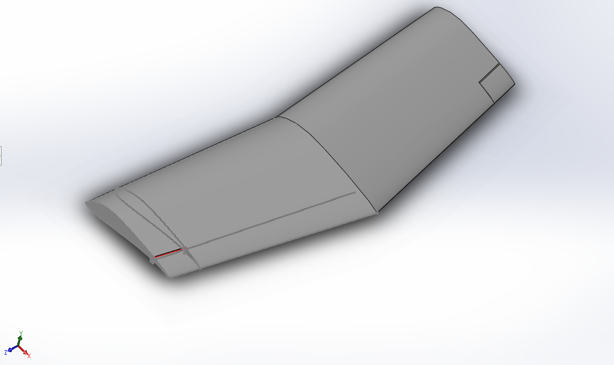
Wing outer mold line along with aileron sections adjacent to wing tips.
After the ruleset was released, our team began work on our experimental plane design that would be used for flight testing during our school's winter break. The '23 season had unique design requirments which include prohibition of fiber-reinforced plastics, rubber bands, and stability assistance. Payload requirements required a regular boxed cargo, which must be carried internally to the aircraft. The cargo had to consist of a support assembly and payload plates that do not utilize tape or velcro. The payload also had to be unloaded within 1 minute after a successful flight.
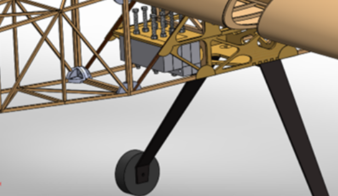
The payload design for the '23 season is particularly impressive because the 18-foot wingspan and large fuselage capacity allowed the plane to carry weight capable of reaching the FAA limit of 55 pounds! My role for this project entailed selecting a geometric steel plate shape, designing the connection method to the wing plate, selecting the plate pattern, running surrounding truss FEA and topological optimization, and manufacturing the payload.
The design process for the payload started with a preliminary analysis of the aircraft's required center of gravity, payload capacity, and log booking of viable payload materials in the shop. The plane's empty (plane without payload components) 'CG' location was found to be 20.45 inches aft from the main wing leading edge. The desired plane's CG, with payload, was determined to be 9.5 inches aft from the main wing leading edge. The plane's 'empty weight' was estimated to be 23.1 pounds meaning a max payload weight of 31.9 pounds. The constraints of this project posed a significant challenge as the materials and processes involved were difficult to get right. The material type had to be dense enough to meet the maximum payload capacity of 31.9 pounds, fit within wing plate dimensions, and be possible for a person to load/unload payload components in under 1 minute. In addition, to save time and money for the team I had to create a design that required the least amount of manufacturing processing and utilized metal materials that we already had in our shop.

CAD of steel payload assembly adjusted for proper CG
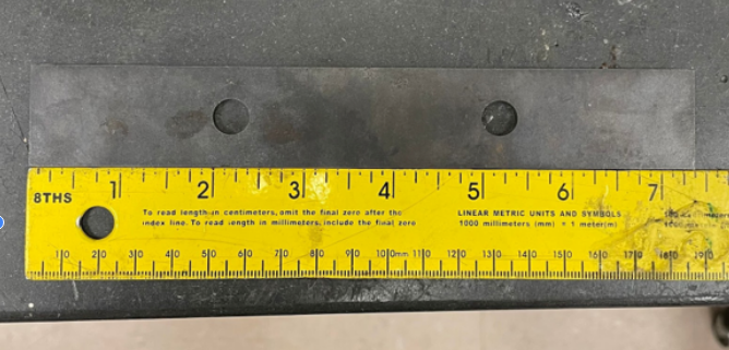
After the payload design was finalized, I began collecting empirical measurements for all the metal inventory in our shop that could be utilized as viable payload components. The metal had to be dense enough so that the CG would shift to the desired location, take up the least amount of space yet be light enough so that we could load the aircraft efficiently. After much analysis, I decided that we would discard the aluminum metal and utilize the steel material we had. The steel payload was prefabricated and the wingplate was created with dense basswood to ensure structural integrity and was laser cut from Solidworks dxf file designs. This project helped me develop my FEA, topological optimization, and CAD experience. It was exciting to be given the responsibility of designing such an important feature of the aircraft and finding the best combination of payload inventory to meet the required design objectives. Finally, this payload design was made to be adjustable along the longitudinal axis of the plane in case necessary design changes from different XP1 mass components caused a CG change. Since the steel bolts were made of plain steel and were 3/8" Ø, all bolts were tightened with a standardized 12 ftlbs to ensure proper fit among all bolts. The torque was validated with turn of nut method instead of a torque gauge, for practice during competition unloading.
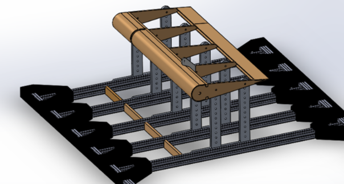
This project encompassed the creation of jig stands tailored for manufacturing empennage control systems and fuselage sections. The purpose of these jigs were to enhance repeatability, accuracy, and ease in production assembly. Functioning as a pivotal element, this equipment played a crucial role in maintaining the quality and functionality of our control surface components, serving as a foundational support for manufacturing processes.
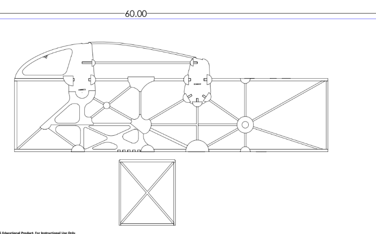
Solidworks DXF drawings like these were printed to 1/16" tolerance. These papers served as a guide while fabricating truss structures for fuselage sections.
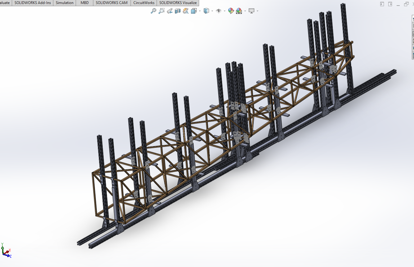
Fuselage Jig Stand
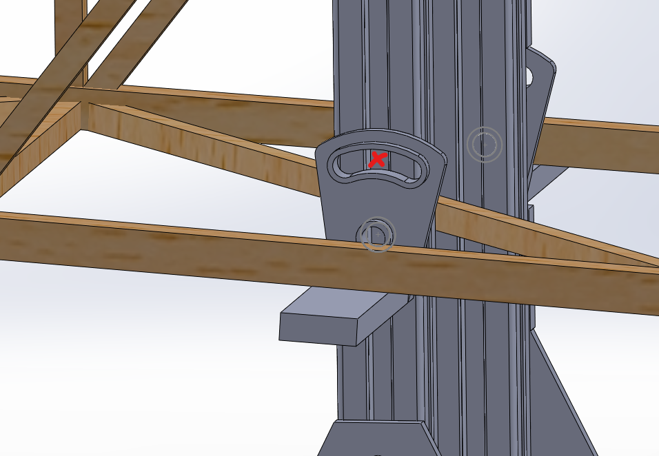
"Jig Shelves" for ensuring proper angled alignment of truss members. "X" marks the location where we would insert flat head screws to the aluminum jigs.
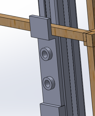
Vertical Stabilizer Jig Stand. Black spacers changed to green for clarity.
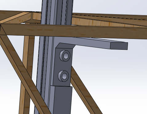
The same jig‑based approach used for the vertical stabilizer was applied to the horizontal stabilizer—both critical for controlling yaw and pitch. To guarantee precise, repeatable builds, I created an empennage test stand featuring movable metal jigs separated by custom 3D‑printed PETG spacers. Production began with laser‑cut ribs and wood spacers; the stand aligned these parts while steam‑bent balsa leading edges and flat balsa trailing edges were glued in place, followed by servo and electronics installation. The chief hurdles were ensuring adequate servo clearance and maintaining a perfect 90° joint between aluminum members, solved by the PETG spacer's integrated notches and center bore. The project deepened my understanding of design‑for‑manufacture, CAD, laser cutting, and the material‑specific handling of plastics, woods, and metals.
During the winter break, our team split up manufacturing work into two winter break sessions "WB1" and "WB2". The first session focused on manufacturing XP1, the second session focused on creating a finalized protype for the competition (CP1).
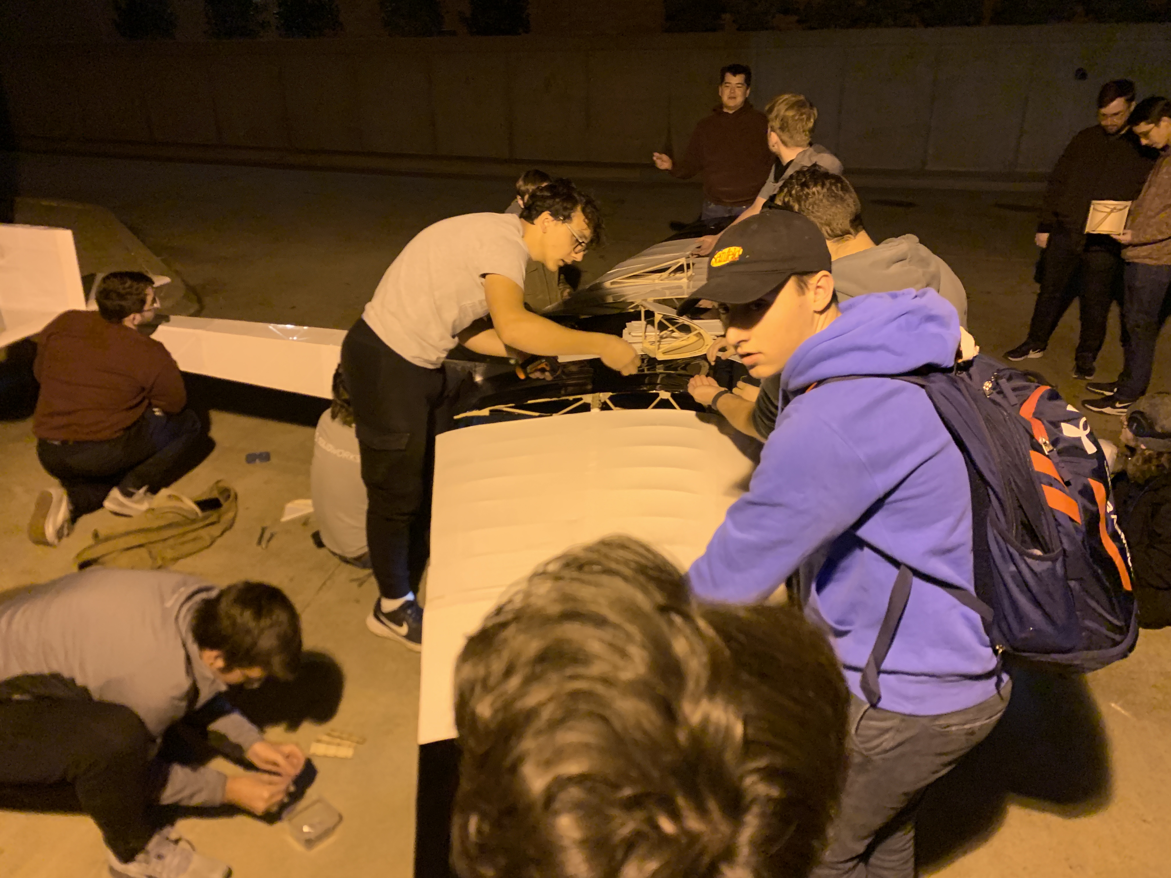
Late night winter break manufacturing.

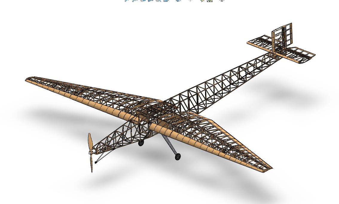
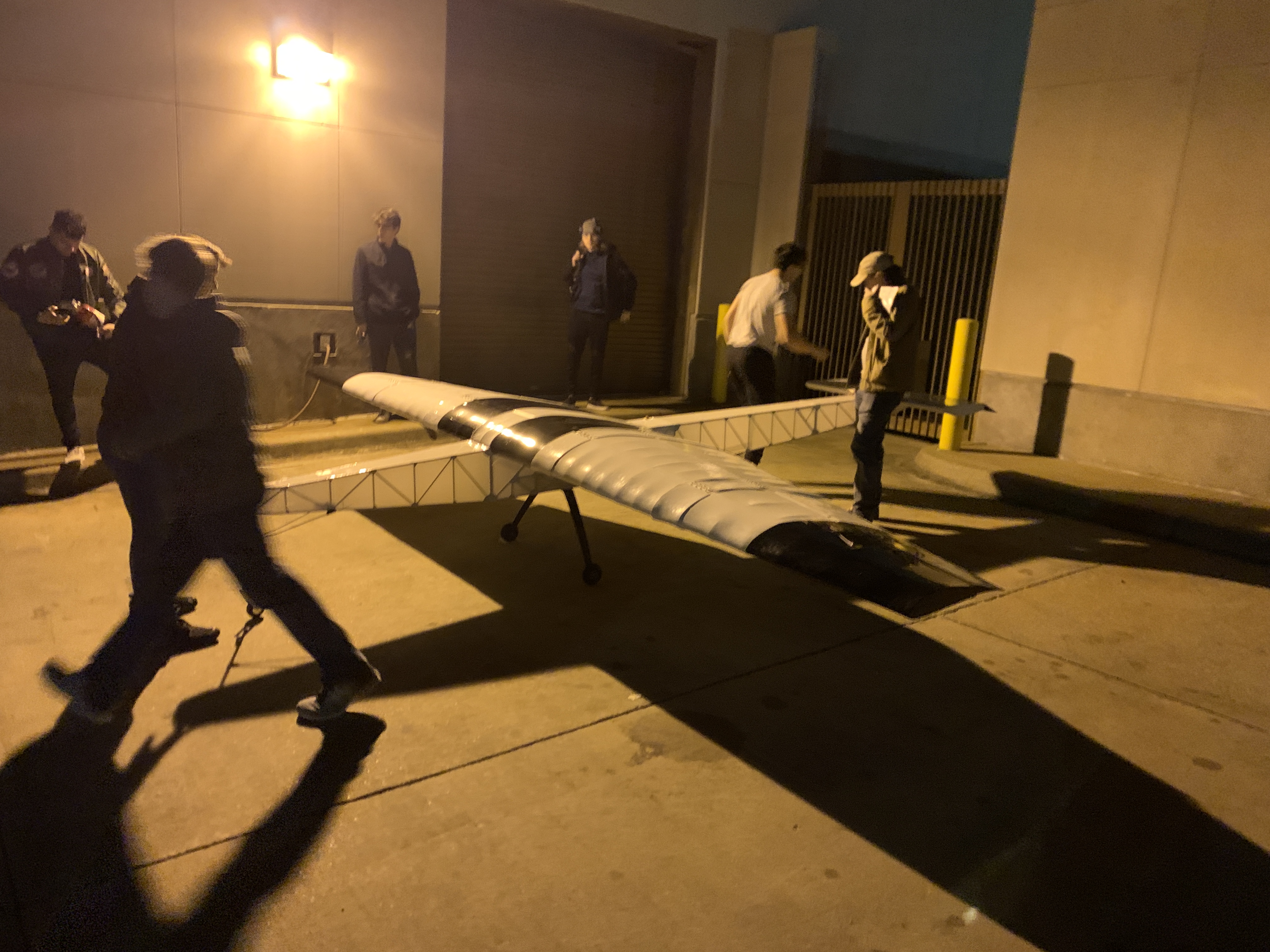
Final Competition Plane Assembly
Empty Plane Weight Percentages
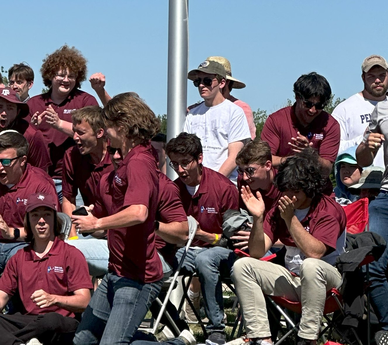
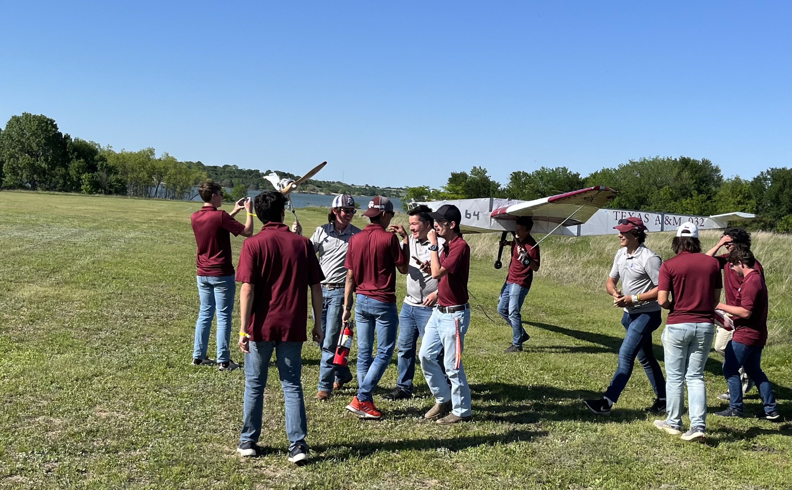
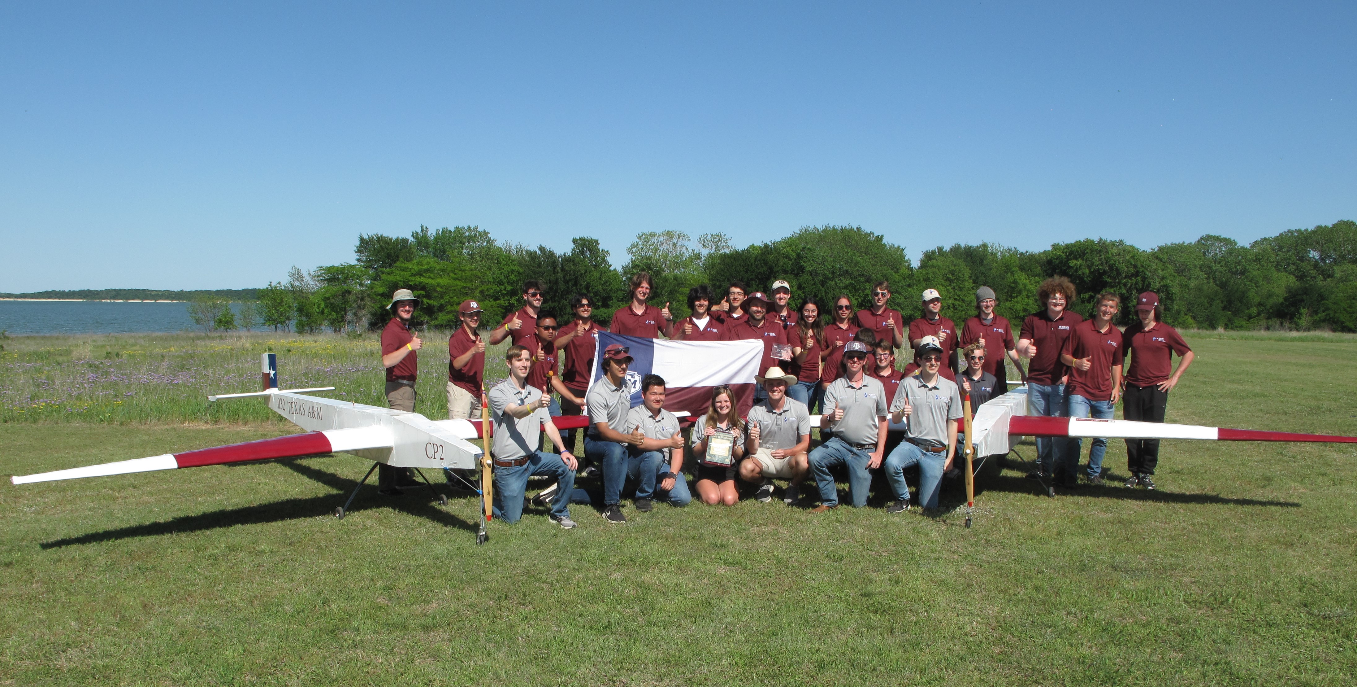
SAE Aero West Competition at Fort Worth, TX.

I show up nodding in approval at around ~2:19
Celebratory loop-de-loop